


Total Racing Products Mission Control – CAN bus Ethanol Content Analyzer With Support For Three Sensors And Three PWM Outputs – Boost Control, Trigger Relays, Control Brushless Pumps, and more! – Universal
Price range: $389.99 through $779.96
-
TOTAL RACING PRODUCTS
Mission Control
SUMMARY
-
Built on TRP’s proven ECA PLUS CAN bus Ethanol Content Analyzer platform
-
Adds three independent PWM outputs for advanced control functions
-
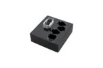
Weather-sealed, carbon fiber infused enclosure with DTM 8-pin main connector, three DT 3-pin analog sensor connectors, and one DT 4-pin PWM output connector
-
Ethanol content and sensor status broadcast via CAN bus
-
Three 0–5 V analog inputs with regulated 5 V supply, ground, and signal pins
-
Supports boost control, relay triggering, brushless pump control, triggering nitrous (with a relay), and other PWM-based logic or auxiliary functions
-
Configurable CAN bus speeds (500 kbps or 1 Mbps) for maximum compatibility (at checkout)
-
Includes three DT 3-pin connectors and one DT 4-pin connector with pins, seals, and cavity plugs for unused inputs or custom sensor harnesses
-
Motorsport-grade wiring and epoxy-sealed housing, safe from heat, fuel, grease, and harsh conditions
DETAILS
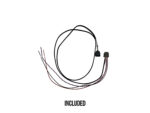
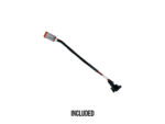
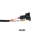
- Includes a TRP Auxiliary Harness that connects to the DT 4 plug:
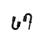
• Pin 1 (12 V) and Pin 2 (Low Side PWM 1) lead to a Bosch EV1 Type Injector Connector, a common industry-standard connector used for boost control solenoids
• Pin 3 (Half Bridge PWM 1) and Pin 4 (Low Side PWM 2) lead to pigtail leads, each labeled with its respective function for easy wiring identification -
PWM connector includes:
• Pin 1 – 12 V Output (suitable for MAC 3-Port Boost Solenoids or other low-draw devices)
• Pin 2 – Low Side PWM Output 1 (–)
• Pin 3 – Half Bridge PWM Output 1 (Active High, 1 amp maximum)
• Pin 4 – Low Side PWM Output 2 (–) -
CAN configuration for existing ECA PLUS ethanol functions is identical, ensuring drop-in compatibility with existing setups
-
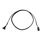
Includes TRP Universal Flex Fuel Sensor Harness (6′ sleeved flex fuel connection + 2′ pigtail for 12V, Ground, CAN Hi, and CAN Lo)
-
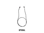
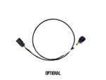
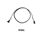
Optional TRP Flex Fuel Extension Harness may be purchased separately
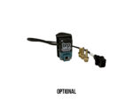
- Optional TRP 3 Port Boost Control Solenoid Kit may be purchased separately
-
Optional TRP Boost Control Solenoid Extension Harness may be purchased separately
-
Optional TRP Universal Sensor Harnesses for plug-and-play connection to aftermarket pressure sensors (TRP, AEM, MoTeC, etc.) may be purchased separately
TECHNICAL INFORMATION
Connector Pinouts
Main Connector
Pin 1: Chassis Ground
Pin 2: CAN Lo
Pin 3: CAN Hi
Pin 4: Flex Fuel Sensor Ground
Pin 5: Flex Fuel Sensor Signal
Pin 6: Flex Fuel Sensor 12V Power
Pin 7: Analog Output (0.5v-4.5v | 0-100% scale)
Pin 8: 12V Power In
Analog Sensor Connectors
Pin A: Ground
Pin B: +5V Sensor Power
Pin C: Sensor Signal
Output Connector
Pin 1: 12V
Pin 2: Low Side PWM 1
Pin 3: Half Bridge PWM 1 (Active High, 1 amp maximum)
Pin 4: Low Side PWM 2
Pinout Illustration
COMING SOON
ATTENTION TUNERS
Mission Control uses the same CAN structure and data settings as the ECA PLUS for ethanol content and analog inputs. If your setup is already tuned for an ECA PLUS, no tuning changes are required in order to use those existing features. A change to your tune is required to calibrate your output configuration and take full advantage of Mission Control’s PWM control capabilities.
Are you using Ecutek?
Ecutek has put together some great information in their knowledge base regarding using this product and it can be seen here:
https://ecutek.atlassian.net/wiki/spaces/SUPPORT/pages/2367258628/370Z+CAN+Input+and+Output#TRP-Mission-Control-CAN-Box
The TRP Mission Control has a CAN configuration with the following specs:
CAN Bus Specs
-
CAN Bus ID Standard (11 bit)
-
CAN Bus ID (HEX): 0x0E1
-
CAN Bus Speed: 500 Kbps or 1 Mbps (configured at checkout)
CAN Data Layout
-
Byte 0 – Flex Fuel Percentage (If Ecutek: CAN Input Channel A)
-
8 bits
- Incoming Hex: 0-64
-
Incoming Decimal: 0-100
- Multipler: 1
-
Offset: 0
- Unit: %
-
Example: Decimal 70 = E70%
- EcuTek Note: For some platforms, the software may expect 0.0–1.0; adjust multiplier to 0.1 accordingly
-
-
Bytes 1–2 – Analog Sensor 1 (If Ecutek: CAN Input Channel B)
-
16 bits, little endian (lo byte first)
-
Incoming Hex: 0-1388
-
Incoming Decimal: 0-5000
-
Multiplier: 1
-
Offset: 0
-
Unit: mV
-
Example: Decimal 1989 = 1989mV or 1.989V
-
-
Bytes 3–4 – Analog Sensor 2 (If Ecutek: CAN Input Channel C)
-
16 bits, little endian (lo byte first)
-
Incoming Hex: 0-1388
-
Incoming Decimal: 0-5000
-
Multiplier: 1
-
Offset: 0
-
Unit: mV
-
Example: Decimal 1989 = 1989mV or 1.989V
-
-
Bytes 5–6 – Analog Sensor 3 (If Ecutek: CAN Input Channel D)
-
16 bits, little endian (lo byte first)
-
Incoming Hex: 0-1388
-
Incoming Decimal: 0-5000
-
Multiplier: 1
-
Offset: 0
-
Unit: mV
-
Example: Decimal 1989 = 1989mV or 1.989V
-
-
Byte 7 – Flex Fuel Sensor Status
- 8 bits
-
0x00 = Sensor OK
-
0x01 = Sensor Fault
Common Analog Sensor Scaling
-
AEM 0-100psi
- PSI (gauge) - Multiplier: 0.025 - Offset: −12.5
- kPa (gauge) - Multiplier: 0.172369 - Offset: −86.1845
-
Bar (gauge) - Multiplier: 0.001724 - Offset: −0.861845
-
TRP and AEM 0-150psi
- PSI (gauge) - Multiplier: 0.0375 - Offset: −18.75
- kPa (gauge) - Multiplier: 0.258554 - Offset: −129.27675
-
Bar (gauge) - Multiplier: 0.002586 - Offset: −1.292767
-
AEM 0-500psi
- PSI (gauge) - Multiplier: 0.125 - Offset: −62.5
- kPa (gauge) - Multiplier: 0.861845 - Offset: −430.9225
-
Bar (gauge) - Multiplier: 0.008618 - Offset: −4.309225
-
AEM 0-2000psi
- PSI (gauge) - Multiplier: 0.5 - Offset: −250
- kPa (gauge) - Multiplier: 3.44738 - Offset: −1723.69
-
Bar (gauge) - Multiplier: 0.034474 - Offset: −17.2369
-
TRP and AEM 3.5 Bar
- PSI (gauge) - Multiplier: 0.012451 - Offset: −6.225471
- kPa (gauge) - Multiplier: 0.085846 - Offset: −42.923125
-
Bar (gauge) - Multiplier: 0.000858 - Offset: −0.429231
- PSI (absolute) - Multiplier: 0.012451 - Offset: 8.470472
- kPa (absolute) - Multiplier: 0.085846 - Offset: 58.401875
-
Bar (absolute) - Multiplier: 0.000858 - Offset: 0.584019
-
TRP and AEM 5.2 Bar
- PSI (gauge) - Multiplier: 0.018736 - Offset: −9.35097
- kPa (gauge) - Multiplier: 0.128939 - Offset: −64.469250
-
Bar (gauge) - Multiplier: 0.001289 - Offset: −0.644693
- PSI (absolute) - Multiplier: 0.018736 - Offset: 5.344973
- kPa (absolute) - Multiplier: 0.128939 - Offset: 36.855750
-
Bar (absolute) - Multiplier: 0.001289 - Offset: 0.368557
-
Omni 4 Bar
- PSI (gauge) - Multiplier: 0.011984 - Offset: 0.516376
- kPa (gauge) - Multiplier: 0.082625 - Offset: 3.560497
-
Bar (gauge) - Multiplier: 0.000826 - Offset: 0.035605
- PSI (absolute) - Multiplier: 0.011984 - Offset: 15.212319
- kPa (absolute) - Multiplier: 0.082625 - Offset: 104.885497
-
Bar (absolute) - Multiplier: 0.000826 - Offset: 1.048855
Output Control Message
- CAN Bus ID Standard (11 bit)
- CAN Bus ID (HEX): 0x335
- CAN Bus Speed: 500 Kbps or 1 Mbps (configured at checkout)
- Transmit Periodicity: 40ms or slower
CAN Data Layout
- Byte 0 – Static
- 8 bits
- MUST BE 0x25 (37 decimal)
- Any other value and the whole message is ignored
- Byte 1 – PWM Frequency, Low-Side PWM 1
- 8 bits
- Range: 10–265Hz
- Offset: +10
- Conversion: Decimal + 10 = Hz
- Example: Sending 0 = 10Hz, 1 = 11Hz, 100 (decimal) = 110Hz
- Byte 2 – PWM Frequency, Low-Side PWM 2
- 8 bits
- Range: 10–265Hz
- Offset: +10
- Conversion: Decimal + 10 = Hz
- Example: Sending 0 = 10Hz, 1 = 11Hz, 100 (decimal) = 110Hz
- Byte 3 – PWM Frequency, High-Side (H-bridge Push-Pull) PWM 1
- 8 bits
- Range: 10–265Hz
- Offset: +10
- Conversion: Decimal + 10 = Hz
- Example: Sending 0 = 10Hz, 1 = 11Hz, 100 (decimal) = 110Hz
- Byte 4 – PWM Duty Cycle, Low-Side PWM 1
- 8 bits
- Range: 0–100%
- Factor: 0.39
- Conversion: Decimal * 0.39 = Duty Cycle %
- Example: Sending 0 = 0%, 100 (dec) = 39%, 255 (dec) = 100%
- Byte 5 – PWM Duty Cycle, Low-Side PWM 2
- 8 bits
- Range: 0–100%
- Factor: 0.39
- Conversion: Decimal * 0.39 = Duty Cycle %
- Example: Sending 0 = 0%, 100 (dec) = 39%, 255 (dec) = 100%
- Byte 6 – PWM Duty Cycle, High-Side (H-bridge Push-Pull) PWM 1
- 8 bits
- Range: 0–100%
- Factor: 0.39
- Conversion: Decimal * 0.39 = Duty Cycle %
- Example: Sending 0 = 0%, 100 (dec) = 39%, 255 (dec) = 100%
- Byte 7 – RESERVED
- 8 bits
- MUST BE 0x00 (other values will be ignored)
- Reserved for future use